AutoCAD® slide files

AutoCAD® slide files and AutoCAD® slide libraries you may use for several purposes, e.g. for making slide shows with AutoCAD®, file exchange in your own applications or for using the preview function in AutoCAD® dialogs (such as the hatch pattern selection dialog in AutoCAD® applications older than AutoCAD® 2000). For slide files you only need AutoCAD®'s onboard tools and commands.

Creating slide files is very easy. Enter the MSLIDE command at the AutoCAD® command prompt. Before using this command zoom in the window which you want to export into the slide file! To read slide files, use the VSLIDE command. To integrate your slide files into a AutoCAD® slide library you should read this chapter.

To implement slide file support to you own applications you'll need the file format description below or find it at Wotsit's format - the programmers resource.


There are 2 different file headers:
     AutoCAD® uses the old header up to AutoCAD® Release 8.
     AutoCAD® Release 9 and later produce slide files with the new header.

Slide files always consist of a header (new header: 31 bytes, old header: 34 bytes) and one or more data records.
All coordinates and sizes written to the slide file reflect the graphics area of the display device from which the slide was created, with point [0,0] located at the lower left corner of the graphics area.

Firstly, this is the new file header:


Field
Bytes
Description
ID String
17
"AutoCAD Slide" CR LF ^Z NUL
type indicator
1
currently set to 86 (decimal), 56 or other value in older files
level indicator
1
currently set to 2
high X dot
2
width of the graphics area - 1 in pixels
high Y dot
2
height of the graphics area - 1 in pixels
aspect ratio
4
graphics area aspect ratio (horizontal size divided by vertical size in inches),
scaled by 10,000,000. This value is always written with the least significant byte first.
hardware fill
2
Either 0 or 2 (value is unimportant)
test number
2
a number (1234 hex) used to determine wether all 2-byte values in the slide were written
with the high-order byte first (Intel 8086-family CPUs)
or the low-order byte first (Motorola 68000-family CPUs)

If you're using AutoCAD® Release 9 or later, it'll produce the header described above and is portable among all computers with AutoCAD Release 9 or later. The old slide header described below (produced with previous versions of AutoCAD®, as well as AutoShade 1.0 and AutoSketch 1.02) looks a bit different:


And secondly, the old file header:


Field
Bytes
Description
ID String
17
"AutoCAD Slide" CR LF ^Z NUL
type indicator
1
currently set to 56 (decimal)
level indicator
1
1 (old format)
high X dot
2
width of the graphics area - 1 in pixels
high Y dot
2
height of the graphics area - 1 in pixels
aspect ratio
8
graphics area aspect ratio (horizontal size divided by vertical size in inches),
written as a floating-point number.
filler byte
1
unused

Difference between old and new file header:

The old format header doesn't contain a test number field. The floating-point aspect ratio value and all 2-byte integers are written in the native format of the CPU that was used to create the file (for 8086-family CPUs, IEEE double-precision, and low-order byte first). Old format slide files are not portable across machine types, but they can be read by any version of AutoCAD running on the same CPU type as the CPU with which the slide was created.

The header is followed by data records. Each data record begins with a 2-byte field whose high-order byte is the record type. Don't forget the byte order (also known as endianess) determined in the test number field in the file header!


Here is a list of all known slide file data records:


Record type
Bytes
Meaning
Description
the from-X coordinate for an ordinary vector.
00 - 7F hex
8
vector
from-Y, to-X and to-Y follow in that order as 2-byte values.
the from point is saved as the last point.
80 - FA hex
-
undefined
reserved for future use
the low-order byte and the following three bytes specify the endpoints
FB hex
5
offset vector
(from-X, from-Y, to-X, to-Y) of a vector, in terms of offsets (-128 to +127)
from the saved last point. The adjusted from point is saved as the last point for use by subsequent vectors.
FC hex
2
end of file
the low-order byte is 00
the low-order byte is always zero. The following two 2-byte values specify
the X and Y coordinates of one vertex of a polygon to be solid filled.
FD hex
6
solid fill
Three to ten such records occur in sequence. A solid fill record with
a negative Y coordinate indicates the start or end of such a flood sequence.
In the start record, the X coordinate indicates the number of vertex records to follow.
common
This is a vector starting at the last point. The low-order byte and the following byte specify
FE hex
3
endpoint
to-X and to-Y in terms of offsets (-128 to +127) from the saved last point.
vector
The adjusted to point is saved as the last point for use by subsequent vectors.
FF hex
2
new color
subsequent vectors are to be drawn using the color number indicated by the low-order byte.

If a slide contains any vectors at all, a new color record will be the first data record. The order of the vectors in a slide, and the order of the endpoints of those vectors, may vary.
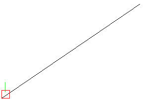
For example, the following is an annotated hex dump of a simple slide file created on an IBM PC/AT with an IBM Enhanced Graphics Adapter. The slide consists of a white diagonal line from the lower-left corner to the upper-right corner of the graphics area, a green vertical line near the lower-left corner, and a small red rectangle at the lower-left corner.

hex dump
Meaning
41 75 74 6F 43 41
44 20 53 6C 69 64
AutoCAD Slide CR LF ^Z NUL
65 0D 0A 1A 00
56
type indicator (56), seems to be an older file
02
level indicator (2)
3C 02
high X dot (572 dec), is the width of the graphics area
24 01
high Y dot (292 dec), is the height of the graphics area
0B 80 DF 00
aspect ratio (14,647,307 / 10,000,000 = 1.46)
02 00
hardware fill (2)
34 12
test number (1234 hex), so it was a x86 based machine
07 FF
new color (7 is white according to the AutoCAD® color dialog)
3C 02 24 01 00 00 00 00
vector from [572,292] to [0,0]. [572,292] becomes "last" point.
03 FF
new color, 3 is green
0F 00 32 00 0F 00 13 00
vector from [15,50] to [15,19]. [15,50] becomes "last" point
01 FF
new color, 1 is red
12 FB E7 12 CE
offset vector from [15+18,50-25] = [33,25] to [15+18,50-50] = [33,0]. [33,25] becomes "last" point.
DF FE 00
common-endpoint vector from [33,25] to [33-33,25+0] = [0,25]. [0,25] becomes "last" point.
00 FE E7
common-endpoint vector from [0,25] to [0+0,25-25] = [0,0]. [0,0] becomes "last" point.
21 FE 00
common-endpoint vector from [0,0] to [0+33,0+0] = [33,0]. [33,0] becomes "last" point.
00 FC
end of file

Slide file example from above:
Slide file example


If you show the slide file from above in AutoCAD® using the
VSLIDE command it will look like the screenshot on the left.

Example   (877 bytes)

last update: 2010-11-16 - 19:40:35.
copyright © by Klaus Burgstaller 2009