AutoCAD® complex linetypes are placed in .LIN files along with simple linetypes. Complex linetypes may contain the same patterns than a simple linetype (lines, dashes and dots) and also symbols like texts and shapes. This linetype can denote utilities, boundaries, contours and so on.
As with simple linetypes, complex lines are dynamically drawn as the user specifies vertices. Shapes an text objects embedded in lines are always displayed completely. They are never trimmed!
The syntax for shape and text object descriptors in a linetype description is:
- for shapes: [shapename,shxfilename] or [shapename,shxfilename,transform]
- for texts: ["string",stylename] or ["string",stylename,transform]
transform is optional an may be any series of the following values (each preceded by a comma): R=## ... relative rotation A=## ... absolute rotation S=## ... scale X=## ... x-offset Y=## ... y-offset where ## is a signed single (signed decimal number like 0.05, -2, ...). Rotations (R and A) are in degrees, scale and offset are DUs (drawing units)
If you use transform be sure to mind the following:
for shapes:shapename must be included, it holds the name of the shape to be elaborated (e.g. CON1 contained in es.shx. If it is omitted, linetype definition fails! shxfilename is the name of a compiled shape definition file (.SHX file) and may be unqualified. Unqualified means, if no path is specified the library path is searched for the file. The scale of the shape is used as a scale factor by which the shape's internally defined scale is multiplied. If the internal scale factor is 0, the S=value alone is used as the scale. A rotation may be relative or absolute. R=value indicates relative or tangential rotation with respect to the lines elaboration. A=value means absolute rotation with respect to the origin.
The value may be followed by a
d ... degrees (default if omitted)
r ... radians
g ... grads
If there's no rotation in the linetype definition, 0(d) relative rotation is used as default. X=value specifies the shift of the shape in the x axis from the linetype definition end vertex.
Default for X=value is 0 if omitted.
This value is NOT scaled by the S=## scale factor!
This also applies to the y offset given in Y=value.
for texts: Fields are defined as follow:"string" is the word to be used. Be sure to use the inverted commas! style specifies the text style. If the text style is omitted, the currently defined style is used. For an explanation for scale, rotation, x-offset and also y-offset check out the for shapes section above.
The main difference between the use of shapes and the use of text is that shapes are associated directly with a shape file and text is associated with a text style in the drawing!
In conclusion let's have a look on an example:
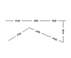
The linetype definition should draw a line intermitted by the string HW (for hot water). Here is the linetype definition:
*HOTWATER, hot water pipe --- HW --- HW --- HW --- HW ---
A,.5,-.2,["HW",STANDARD,S=.1,R=0.0,X=-0.1,Y=-.05],-.2
Here are the explainations:

A ... alignment, is always A!
.5 ... draws a line of 0.5 DU length
-.2 ... draws a blank segment
"HW" ... is the string to be inserted
S=.1 ... the scale is 0.0
R=0.0 ... says that the text has the same orientation
than the line! (as you can see in the example image)
X=-0.1,Y=-.05 ... places the text where you like it
-.2 ... then let's draw another blank.
To change the text style you have to format the textstyle STANDARD (or any other text style you specify in the linetype definition) !

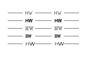
Here you see different fonts in our HW linetype definition:
txt.shx, Arial, Times New Roman, and some more ...


